Home About

How to Use TopoDrive

Running TopoDrive involves seven steps, as described below. To begin each step, click the corresponding button at the top of the window.
At Step 6, two options are available. Follow Step 6a to compute flow paths, or Step 6b to set up fluid particles.
Step 1: Specify the length of the flow domain
  • Click the "Start" button.

  • Enter the model length (in meters) and the vertical exaggeration. (Set the vertical exaggeration to 1 so that that horizontal scale is equal to the vertical scale.)

  • Click OK.

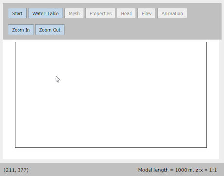
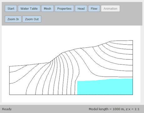
TopoDrive draws the sides and the base of the flow domain.

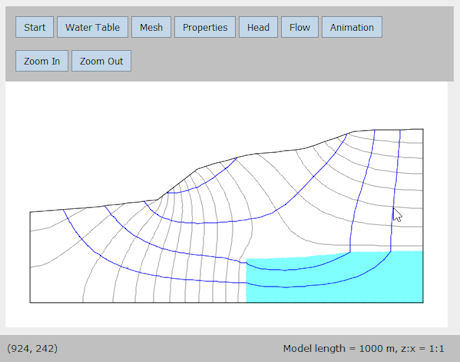
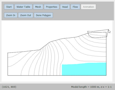
Note that the horizontal and vertical coordinates of the cursor are shown at the lower left corner of the window.

TopoDrive program window during Step 1
Step 2: Draw the water table
  • Click the "Water Table" button.

  • TopoDrive shows a reminder to draw the water table from left to right.

  • Click OK.

  • Place the cursor at left boundary, or just to the left of it. Click the left starting point of the water table.

  • Move the cursor to the right and click at points along the water table.

  • Click the last point at the right boundary, or just to the right of it.

TopoDrive program window during Step 2
Step 3: Specify the mesh
  • Click the "Mesh" button.

  • Enter the number of columns and rows to discretize the flow domain. (Suggestion: Use between 40 to 100 columns. The number of row can be fewer than the number of columns.)

  • Click OK.

TopoDrive generates a deformed rectangular mesh and then splits each rectangular element into two triangular elements.

TopoDrive program window during Step 3
Step 4: Assign hydraulic properties
  • Click the "Properties" button.

  • Select "isotropic" or "anisotropic".

  • (Optional) Change the hydraulic conductivity and/or porosity values.

  • Click on a color icon to select the corresponding property values.

  • Click OK.

  • Draw a polygon to enclose those elements to be assigned the selected property values. A polygon is drawn by clicking at its vertices.

  • To finish drawing the polygon, double click the last vertex.

  • An alternative way to finish drawing the polygon is to single click the last vertex and then click the "Done Polygon" button.

Repeat the above steps to assign hydraulic properties to other zones in the aquifer.

TopoDrive program window during Step 4
Step 5: Compute hydraulic head
  • Click the "Head" button.

  • Select the number of contour intervals to be drawn.

  • Click "Compute".

Head contours are equally spaced between the highest and the lowest head.

To find the hydraulic head of a contour line, place the cursor at the point where the contour line meets the water table. The elevation of this point is the hydraulic head of the contour line.

TopoDrive program window during Step 5
Step 6a: Compute groundwater flow paths
  • Click the "Flow" button.

  • Select "Flow path tracking".

  • Select the direction of flow path tracking.

  • Click OK.

  • Click anywhere in the flow domain to track the flow path from that point in the direction(s) specified above.

  • Click on additional points in the flow domain to track additional flow paths.

TopoDrive program window during Step 6a
Step 6b: Set up fluid particles
  • Click the "Flow" button.

  • Select "Particle movement".

  • Enter the initial particle spacing (in meters). As a general guide, use a spacing that is between 1/100 and 1/1000 of the model domain length.

  • Click OK.

  • Draw a polygon to outline the initial location of a cluster of fluid particles. Keep the polygon relatively small to avoid having too many particles.

  • After the polygon is drawn, it will be filled with particles at the prescribed spacing.

  • (Optional) Draw additional polygons to create additional clusters of particles.

TopoDrive program window during Step 6b
Step 7: Animate flow paths or particle movement
  • Click the "Animation" button.

  • Set the animation speed by specifying the amount of travel time (in days or years) that is equal to 1 second of animation time.

  • Set the animation smoothness by specifying the number of frames per second. (The default setting of 10 frames per second is usually adequate.)

  • Click OK.

  • To start the animation, click anywhere inside the window, below the buttons.

  • Additional clicks alternately freeze and unfreeze the animation.

Travel time is shown at the bottom of the window.

TopoDrive program window during Step 7

Animation of particle movement